A padlock and chain on a rusted gate

Using #NetworkFirewall and #Route53 #DNS #Firewall to protect a private subnet’s egress traffic in #AWS

I wrote this post in January 2023, and it’s been languishing in my Drafts folder since then. I’ve had a look through it, and I can’t see any glaring reasons why I didn’t publish it so… it’s published… Enjoy 😁

If you’ve ever built a private subnet in AWS, you know it can be a bit tricky to get updates from the Internet – you end up having a NAT gateway or a self-managed proxy, and you can never be 100% certain that the egress traffic isn’t going somewhere you don’t want it to.

In this case, I wanted to ensure that outbound HTTPS traffic was being blocked if the SNI didn’t explicitly show the DNS name I wanted to permit through, and also, I only wanted specific DNS names to resolve. To do this, I used AWS Network Firewall and Route 53 DNS Firewall.

I’ve written this blog post, and followed along with this, I’ve created a set of terraform files to represent the steps I’ve taken.

The Setup

Let’s start this story from a simple VPC with three private subnets for my compute resources, and three private subnets for the VPC Endpoints for Systems Manager (SSM).

Here’s our network diagram, with the three subnets containing the VPC Endpoints at the top, and the three instances at the bottom.

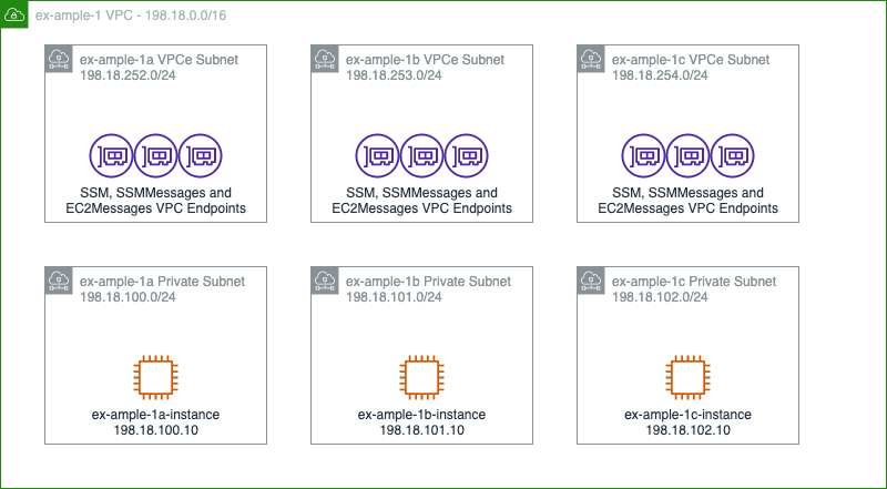
I’ve created a tag in my Github repo at this “pre-changes” state, called step 1.

At this point, none of those instances can reach anything outside the network, with the exception of the SSM environment. So, we can’t install any packages, we can’t get data from outside the network or anything similar.

Getting Protected Internet Access

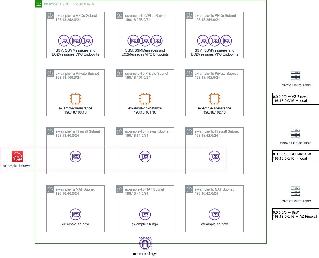
In order to get internet access, we need to add 4 things;

  1. An internet gateway
  2. A NAT gateway in each AZ
  3. Which needs three new subnets
  4. And three Elastic IP addresses
  5. Route tables in all the subnets

To clarify, a NAT gateway acts like a DSL router. It hides the source IP address of outbound traffic behind a single, public IP address (using an Elastic IP from AWS), and routes any return traffic back to wherever that traffic came from. To reduce inter-AZ data transfer rates, I’m putting one in each AZ, but if there’s not a lot of outbound traffic or the outbound traffic isn’t critical enough to require resiliency, this could all be centralised to a single NAT gateway. To put a NAT gateway in each AZ, you need a subnet in each AZ, and to get out to the internet (by whatever means you have), you need an internet gateway and route tables for how to reach the NAT and internet gateways.

We also should probably add, at this point, four additional things.

  1. The Network Firewall
  2. Subnets for the Firewall interfaces
  3. Stateless Policy
  4. Stateful Policy

The Network Firewall acts like a single appliance, and uses a Gateway Load Balancer to present an interface into each of the availability zones. It has a stateless policy (which is very fast, but needs to address both inbound and outbound traffic flows) to do IP and Port based filtering (referred to as “Layer 3” filtering) and then specific traffic can be passed into a stateful policy (which is slower) to do packet and flow inspection.

In this case, I only want outbound HTTPS traffic to be passed, so my stateless rule group is quite simple;

  • VPC range on any port → Internet on TCP/443; pass to Stateful rule groups
  • Internet on TCP/443 → VPC range on any port; pass to Stateful rule groups

I have two stateful rule groups, one is defined to just allow access out to example.com and any relevant subdomains, using the “Domain List” stateful policy item. The other allows access to example.org and any relevant subdomains, using a Suricata stateful policy item, to show the more flexible alternative route. (Suricata has lots more filters than just the SNI value, you can check for specific SSH versions, Kerberos CNAMEs, SNMP versions, etc. You can also add per-rule logging this way, which you can’t with the Domain List route).

These are added to the firewall policy, which also defines that if a rule doesn’t match a stateless rule group, or an established flow doesn’t match a stateful rule group, then it should be dropped.

New network diagram with more subnets and objects, but essentially, as described in the paragraphs above. Traffic flows from the instances either down towards the internet, or up towards the VPCe.

I’ve created a tag in my Github repo at this state, with the firewall, NAT Gateway and Internet Gateway, called step 2.

So far, so good… but why let our users even try to resolve the DNS name of a host they’re not permitted to reach. Let’s turn on DNS Firewalling too.

Turning on Route 53 DNS Firewall

You’ll notice that in the AWS Network Firewall, I didn’t let DNS out of the network. This is because, by default, AWS enables Route 53 as it’s local resolver. This lives on the “.2” address of the VPC, so in my example environment, this would be 198.18.0.2. Because it’s a local resolver, it won’t cross the Firewall exiting to the internet. You can also make Route 53 use your own DNS servers for specific DNS resolution (for example, if you’re running an Active Directory service inside your network).

Any Network Security Response team members you have working with you would appreciate it if you’d turn on DNS Logging at this point, so I’ll do it too!

In March 2021, AWS announced “Route 53 DNS Firewall”, which allow this DNS resolver to rewrite responses, or even to completely deny the existence of a DNS record. With this in mind, I’m going to add some custom DNS rules.

The first thing I want to do is to only permit traffic to my specific list of DNS names – example.org, example.com and their subdomains. DNS quite likes to terminate DNS names with a dot, signifying it shouldn’t try to resolve any higher up the chain, so I’m going to make a “permitted domains” DNS list;

example.com.
example.org.
*.example.com.
*.example.org.

Nice and simple! Except, this also stops me from being able to access the instances over SSM, so I’ll create a separate “VPCe” DNS list:

ssm.ex-ample-1.amazonaws.com.
*.ssm.ex-ample-1.amazonaws.com.
ssmmessages.ex-ample-1.amazonaws.com.
*.ssmmessages.ex-ample-1.amazonaws.com.
ec2messages.ex-ample-1.amazonaws.com.
*.ec2messages.ex-ample-1.amazonaws.com.

Next I create a “default deny” DNS list:

*.

And then build a DNS Firewall Policy which allows access to the “permitted domains”, “VPCe” lists, but blocks resolution of any “default deny” entries.

I’ve created a tag in my Github repo at this state, with the Route 53 DNS Firewall configured, called step 3.

In conclusion…

So there we have it. While the network is not “secure” (there’s still a few gaps here) it’s certainly MUCH more secure than it was, and it certainly would take a lot more work for anyone with malicious intent to get your content out.

Feel free to have a poke around, and leave comments below if this has helped or is of interest!

"Untitled" by "Ryan Dickey" on Flickr

Run an Ansible Playbook against a Check Point Gaia node running R80+

Late Edit – 2019-11-05: Ansible 2.9 has some Check Point modules for interacting with the Check Point Manager API which are actually Idempotent, and if you’re running Ansible <=2.8, there are some non-idempotent modules available directly from Check Point. This post is about interacting with the OS. The OS might now be much more addressable using ansible_connection=ssh!

In Check Point Gaia R77, if you wanted to run Ansible against this node, you were completely out of luck. The version of Python on the host was broken, modules were missing and … well, it just wouldn’t work.

Today, I’m looking at running some Ansible playbooks against Check Point R80 nodes. Here’s some steps you need to get through to make it work.

  1. Make sure the user that Ansible is going to be using has the shell /bin/bash. If you don’t have this set up, the command is: set user ansible shell /bin/bash.
  2. If you want a separate user account to do ansible actions, run these commands:
    add user ansible uid 9999 homedir /home/ansible
    set user ansible password-hash $1$D3caF9$B4db4Ddecafbadnogoood (note this hash is not valid!)
    add rba user ansible roles adminRole
    set user ansible shell /bin/bash
  3. Make sure your inventory specifies the right path for your Python binary. In the next code block you’ll see my inventory for three separate Check Point R80+ nodes. Note that I’ll only be targetting the “checkpoint” group, but that I’m using the r80_10, r80_20 and r80_30 groups to load the variables into there. I could, alternatively, add these in as values in group_vars/r80_10.yml and so on, but I find keeping everything to do with my connection in one place much cleaner. The python interpreter is in a separate path for each version time, and if you don’t specify ansible_ssh_transfer_method=piped you’ll get a message like this: [WARNING]: sftp transfer mechanism failed on [cpr80-30]. Use ANSIBLE_DEBUG=1 to see detailed information (fix from Add pipeline-ish method using dd for file transfer over SSH (#18642) on the Ansible git repo)
[checkpoint]
cpr80-10        ansible_user=admin      ansible_password=Sup3rS3cr3t-
cpr80-20        ansible_user=admin      ansible_password=Sup3rS3cr3t-
cpr80-30        ansible_user=admin      ansible_password=Sup3rS3cr3t-

[r80_10]
cpr80-10

[r80_20]
cpr80-20

[r80_30]
cpr80-30

[r80_10:vars]
ansible_ssh_transfer_method=piped
ansible_python_interpreter=/opt/CPsuite-R80/fw1/Python/bin/python

[r80_20:vars]
ansible_ssh_transfer_method=piped
ansible_python_interpreter=/opt/CPsuite-R80.20/fw1/Python/bin/python

[r80_30:vars]
ansible_ssh_transfer_method=piped
ansible_python_interpreter=/opt/CPsuite-R80.30/fw1/Python/bin/python

And there you have it, one quick “ping” check later…

$ ansible -m 'ping' -i hosts checkpoint
cpr80-10 | SUCCESS => {
    "changed": false,
    "ping": "pong"
}
cpr80-30 | SUCCESS => {
    "changed": false,
    "ping": "pong"
}
cpr80-20 | SUCCESS => {
    "changed": false,
    "ping": "pong"
}

One quick word of warning though, don’t use gather_facts: true or the setup: module. Both of these still rely on missing libraries on the Check Point nodes, and won’t work… But then again, you can get whatever you need from shell commands….. right? ;)

Featured image is “Untitled” by “Ryan Dickey” on Flickr and is released under a CC-BY license.

"Juniper NetScreen 25 Firewall front" by "jackthegag" on Flickr

Standard Firewall Rules

One of the things I like to do is to explain how I set things up, but a firewall is one of those things that’s a bit complicated, because it depends on your situation, and what you’re trying to do in your environment. That said, there’s a template that you can probably get away with deploying, and see if it works for your content, and then you’ll see where to add the extra stuff from there. Firewall policies typically work from the top down.

This document will assume you have a simple boundary firewall. This simple firewall has two interfaces, the first being an “Outside” interface, connected to your ISP, with an IPv4 address of 192.0.2.2/24 and a default gateway of 192.0.2.1, it also has a IPv6 address of 2001:db8:123c:abd::2/64 and a default gateway address of 2001:db8:123c:abd::1. The second “Inside” interface, where your protected network is attached, has an IPv4 address of 198.51.100.1/24 and an IPv6 address of 2001:db8:123d:abc::1/64. On this inside interface, the firewall is the default gateway for the inside network.

I’ll be using simple text rules to describe firewall policies, following this format:

Source Interface: <outside | inside>
Source IP Address: <x.x.x.x/x | "any">
NAT Source IP Address: <x.x.x.x/x | no>
Destination Interface: <outside | inside>
Destination IP Address: <x.x.x.x/x | "any">
NAT Destination IP Address: <x.x.x.x/x | no>
Destination Port: <tcp | udp | icmp | ip>/<x>
Action: <allow | deny | reject>
Log: <yes | no>
Notes: <some commentary if required>

In this model, if you want to describe HTTP access to a web server, you might write the following policy:

Source Interface: outside
Source IP Address: 0.0.0.0/0 (Any IP)
NAT Source IP Address: no
Destination Interface: inside
Destination IP Address: 192.0.2.2 (External IP)
NAT Destination IP Address: 198.51.100.2 (Internal IP)
Destination Port: tcp/80
Action: allow
Log: yes

So, without further waffling, let’s build a policy. By default all traffic will be logged. In high-traffic environments, you may wish to prevent certain traffic from being logged, but on the whole, I think you shouldn’t really lose firewall logs unless you need to!

Allowing established, related and same-host traffic

This rule is only really needed on iptables based firewalls, as all the commercial vendors (as far as I can tell, at least) already cover this as “standard”. If you’re using UFW (a wrapper to iptables), this rule is covered off already, but essentially it goes a bit like this:

Source Interface: lo (short for "local", where the traffic never leaves the device)
Source IP Address: any
NAT Source IP Address: no
Destination Interface: lo
Destination IP Address: any
NAT Destination IP Address: no
Destination Port: any
Action: allow
Log: no
Notes: This above rule permits traffic between localhost addresses (127.0.0.0/8) or between public addresses on the same host, for example, between two processes without being blocked.
flags: Established OR Related
Action: allow
Log: no
Notes: This above rule is somewhat special, as it looks for specific flags on the packet, that says "If we've already got a session open, let it carry on talking".

Dropping Noisy Traffic

In a network, some proportion of the traffic is going to be “noisy”. Whether it’s broadcast traffic from your application that uses mDNS, or the Windows File Share trying to find like-minded hosts to exchange data… these can fill up your logs, so lets drop the broadcast and multicast IPv4 traffic, and not log them.

Source Interface: any
Source IP Address: 0.0.0.0/0
NAT Source IP Address: no
Destination Interface: any
Destination IP Address: 255.255.255.255 (global broadcast), 192.0.2.255 ("outside" broadcast), 198.51.100.255 ("inside" broadcast) and 224.0.0.0/4 (multicast)
NAT Destination IP Address: no
Destination Port: any
Action: deny
Log: no
Notes: The global and local broadcast addresses are used to "find" other hosts in a network, whether that's a DHCP server or something like mDNS. Dropping this prevents the traffic from appearing in your logs later.

Permitting Management Traffic

Typically you want to trust certain machines to access or be accessed by this host – whether it’s your SYSLOG collector, or the box that can manage the firewall policy, so here we’ll create a policy that lets these in.

Source Interface: inside
Source IP Address: 198.51.100.2 and 2001:db8:123d:abc::2 (Management IP)
NAT Source IP Address: no
Destination Interface: inside
Destination IP Address: 198.51.100.1 and 2001:db8:123d:abc::1 (Firewall IP)
NAT Destination IP Address: no
Destination Port: SSH (tcp/22)
Action: permit
Log: yes
Notes: Allow inbound SSH access. You're unlikely to need more inbound ports, but if you do - customise them here.
Source Interface: inside
Source IP Address: 198.51.100.1 and 2001:db8:123d:abc::1 (Firewall IP)
NAT Source IP Address: no
Destination Interface: inside
Destination IP Address: 198.51.100.2 and 2001:db8:123d:abc::2 (Management IP)
NAT Destination IP Address: no
Destination Port: SYSLOG (udp/514)
Action: permit
Log: yes
Notes: Allow outbound SYSLOG access. Tailor this to outbound ports you need.

Allowing Control Traffic

ICMP is a protocol that is fundamental to IPv4 and IPv6. Commonly used for Traceroute and Ping, but also used to perform REJECT responses and that sort of thing. We’re only going to let it be initiated *out* not in. Some people won’t allow this rule, or tailor it to more specific destinations.

Source Interface: inside
Source IP Address: any
NAT Source IP Address: 192.0.2.2 (The firewall IP address which may be replaced with 0.0.0.0 indicating "whatever IP address is bound to the outbound interface")
Destination Interface: outside
Destination IP Address: any
NAT Destination IP Address: no
Destination Port: icmp
Action: allow
Log: yes
Notes: ICMPv4 and ICMPv6 are different things. This is just the ICMPv4 version. IPv4 does require NAT, hence the difference from the IPv6 version below.
Source Interface: inside
Source IP Address: any
NAT Source IP Address: no
Destination Interface: outside
Destination IP Address: any
NAT Destination IP Address: no
Destination Port: icmpv6
Action: allow
Log: yes
Notes: ICMPv4 and ICMPv6 may be treated as different things. This is just the ICMPv6 version. IPv6 does not require NAT.

Protect the Firewall

There should be no other traffic going to the Firewall, so let’s drop everything. There are two types of “Deny” message – a “Reject” and a “Drop”. A Reject sends a message back from the host which is refusing the connection – usually the end server to say that the service didn’t want to reply to you, but if there’s a box in the middle – like a firewall – this reject (actually an ICMP packet) comes from the firewall instead. In this case it’s identifying that the firewall was refusing the connection for the node, so it advertises the fact the end server is protected by a security box. Instead, firewall administrators tend to use Drop, which just silently discards the initial request, leaving the initiating end to “Time Out”. You’re free to either “Reject” or “Drop” whenever we show “Deny” in the below policies, but bear it in mind that it’s less secure to use Reject than it is to Drop.

Source Interface: any
Source IP Address: any
NAT Source IP Address: no
Destination Interface: any
Destination IP Address: 192.0.2.2, 2001:db8:123c:abd::2, 198.51.100.1 and 2001:db8:123d:abc::1 (may also be represented as :: or 0.0.0.0 depending on the platform)
NAT Destination IP Address: no
Destination Port: any
Action: deny
Log: no
Notes: Drop everything targetted at the firewall IPs. If you have more NICs or additional IP addresses on the firewall, these will also need blocking.

“Normal” Inbound Traffic

After you’ve got your firewall protected, now you can sort out your “normal” traffic flows. I’m going to add a single inbound policy to represent the sort of traffic you might want to configure (in this case a simple web server), but bear in mind some environments don’t have any “inbound” rules (for example, most homes would be in this case), and some might need lots and lots of inbound rules. This is just to give you a flavour on what you might see here.

Source Interface: outside
Source IP Address: any
NAT Source IP Address: no
Destination Interface: inside
Destination IP Address: 192.0.2.2 (External IP)
NAT Destination IP Address: 198.51.100.2 (Internal IP)
Destination Port: tcp/80 (HTTP), tcp/443 (HTTPS)
Action: allow
Log: yes
Notes: This is the IPv4-only rule. Note a NAT MUST be applied here.
Source Interface: outside
Source IP Address: any
NAT Source IP Address: no
Destination Interface: inside
Destination IP Address: 2001:db8:123d:abc::2
NAT Destination IP Address: no
Destination Port: tcp/80 (HTTP), tcp/443 (HTTPS)
Action: allow
Log: yes
Notes: This is the IPv6-only rule. Note that NO NAT is required (but, you may wish to perform NAT, depending on your environment).

“Normal” Outbound Traffic

If you’re used to a DSL router, that basically just allows all outbound traffic. We’re going to implement that here. If you want to be more specific about things, you’d define your outbound rules like the inbound rules in the block above… but if you’re not that worried, then this rule below is generally going to be all OK :)

Source Interface: inside
Source IP Address: any
NAT Source IP Address: 192.0.2.2 (The firewall IP address which may be replaced with 0.0.0.0 indicating "whatever IP address is bound to the outbound interface")
Destination Interface: outside
Destination IP Address: any
NAT Destination IP Address: no
Destination Port: any
Action: allow
Log: yes
Notes: This is just the IPv4 version. IPv4 does require NAT, hence the difference from the IPv6 version below.
Source Interface: inside
Source IP Address: any
NAT Source IP Address: no
Destination Interface: outside
Destination IP Address: any
NAT Destination IP Address: no
Destination Port: any
Action: allow
Log: yes
Notes: This is just the IPv6 version. IPv6 does not require NAT.

Drop Rule

Following your permit rules above, you now need to drop everything else. Fortunately, by now, you’ve “white-listed” all the permitted traffic, so now we can just drop “everything”. So, let’s do that!

Source Interface: any
Source IP Address: any
NAT Source IP Address: no
Destination Interface: any
Destination IP Address: any
NAT Destination IP Address: no
Destination Port: any
Action: deny
Log: yes

And so that is a basic firewall policy… or at least, it’s the template I tend to stick to! :)

TCPDump Made Easier Parody Book Cover, with the subtitle "Who actually understands all those switches?"

One to use: tcpdump101.com

I’m sure that anyone doing operational work has been asked at some point if you can run a “TCPDump” on something, or if you could get a “packet capture” – if you have, this tool (as spotted on the Check Point community sites) might help you!

https://tcpdump101.com

Using simple drop-down fields for filters and options and using simple prompts, this tool tells you how to run each of the packet capturing commands for common firewall products (FortiGate, ASA, Check Point) and the more generic tcpdump tool (indicated by a Linux Penguin, but it runs on all major desktop and server OSs, as well as rooted Android devices).

Well worth a check out!

Running Streisand to provide VPN services on my home server

A few months ago I was a guest on The Ubuntu Podcast, where I mentioned that I use Streisand to terminate my VPN connections. I waffled and blathered a bit about how I set it up, but in the end it comes down to this:

  1. Install Virtualbox on my Ubuntu server. Include the “Ext Pack”.
  2. Install Vagrant on my Ubuntu server.
  3. Clone the Streisand Github repository to my Ubuntu server.
  4. Enter that cloned repository, and edit the Vagrantfile as follows:
    1. Add the line “config.vm.boot_timeout = 65535” after the one starting “config.vm.box”.
    2. Change the streisand.vm.hostname line to be an appropriate hostname for my network, and add on the following line (replace “eth0” with the attached interface on your network and “192.0.2.1” with an unallocated static IP address from your network):
      streisand.vm.network "public_network", bridge: "eth0", ip: "192.0.2.1", :use_dhcp_assigned_default_route => false
    3. Add a “routing” line, as follows (replace 192.0.2.254 with your router IP address):
      streisand.vm.provision "shell", run: "always", inline: "ip route add 0.0.0.0/1 via 192.0.2.254 ; ip route add 128.0.0.0/1 via 192.0.2.254"
    4. Comment out the line “streisand_client_test => true”
    5. Amend the line “streisand_ipv4_address” to reflect the IP address you’ve put above in 4.2.
    6. Remove the block starting “config.vm.define streisand-client do |client|”
  5. Run “vagrant up” in that directory to start the virtual machine. Once it’s finished starting, there will be a folder called “Generated Docs” – open the .html file to see what credentials you must use to access the server. Follow it’s instructions.
  6. Once it’s completed, you should open ports on your router to the IP address you’ve specified. Typically, at least, UDP/500 and UDP/4500 for the IPsec service, UDP/636 for the OpenVPN service and TCP/4443 for the OpenConnect service.

Building a WPA2 Protected Wireless Access Extender for Jogglers using Ubuntu 12.04

Shesh! What a lot of keywords in the title!

For those who don’t know what some of those key words were, I’ll break down the title

  • Ubuntu is a Linux distribution, and 12.04 is the version number of the latest Long Term Stable version.
  • Joggler is the name of a device sold by O2 a couple of years ago. It is a re-branded OpenPeak tablet.
  • A Wireless Access Extender is a device like a WiFi enabled router, but it uses the same DHCP pool and should use the same SSID name and WPA2 passphrase.
  • WPA2 is the latest incarnation of the WiFi security protocol. It is currently (at this time, as far as I know) uncracked, unlike WPA1 or WEP.

So, now that we know what I’m talking about, let’s look at what components we will be using today.

  • An O2 Joggler. EBay lists them from between £30 and £100. They originally sold for around £100, but got popular when O2 dropped the price to £50. They are no longer available for sale from O2, hence EBay.
  • A wired network connection. I’m using a pair of Ethernet over Power (or “HomePlug”) devices to let me position this device in a useful place in my house. I’ve had a lot of success with the 200M devices sold by 7DayShop.com, but if I were buying new today, I’d probably stretch up to the 500M devices, as they will be Half Duplex (like a narrow street permitting traffic only one way at a time), and will loose some data due to interference and “collisions” – where two devices on the Ethernet over Power “network” are talking at the same time. Ultimately, you won’t get the equivalent to 100M Full Duplex with the 200M devices, but should do with the 500M devices.
  • A USB stick. This needs to be 4Gb or greater, but not all devices are suitable. I bought some 4Gb sticks from 7DayShop.com and found they only actually held around 3.5Gb… making them unsuitable. I bought three 8Gb sticks from 7DayShop.com, but only used one for this task!
  • A Ubuntu 12.04 install. Actually, I used the Xubuntu 12.04 image, because I didn’t need everything that Ubuntu 12.04 gave me. This is a special non-official build of Xubuntu, customised for Joggler hardware and it’s touchscreen, and is what I’ll be moving all my Jogglers in the house to, eventually, however, the principals in making all of this stuff work will apply just as much to Ubuntu as it would Xubuntu – special build or not!
  • Once installed, you’ll use a combination of VNC and SSH to manage your device, these will be through the X11VNC project and OpenSSH-Server. You should have an SSH client (for Linux/Mac, ssh should be fine, for Windows, use PuTTY) and a VNC client (for Ubuntu, I use Remmina, for Windows, I use TightVNC).

So, you’ve got all your goodies, and you’re ready to go. Let’s do this!

  1. Transfer the Xubuntu image to the USB stick. This is a simple task, and is clearly documented on the site where I got the Xubuntu image from, and involves you copying the image directly to the USB stick, not to one of it’s partitions. It sounds complicated, it really isn’t.
  2. Stick the Xubuntu stick into the side of the Joggler. Get used to that shape, as it’s going to be in the side of that from now on. This is because the Linux distribution needs more than the 1Gb that the Joggler holds internally.
  3. Plug in the HomePlug device – make it as close to the wall as you can make it! I’ve had experience of it being three 4way plug strips away from the wall and it worked fine, but I’ve also had the same HomePlug only one 4way away, and it’s completely failed to work, and had to juggle all my sockets to get it plugged directly into the wall. I think it may be down to the number of “noisy” plugs in the same 4way, but I can’t be sure. Just experiment!
  4. Plug your Ethernet cable between the HomePlug and the Joggler.
  5. Power on the Joggler. It will start up with an O2 logo (or possibly an “OpenPeak” logo – depends on when the device was manufactured)  – sometimes either of these may corrupt or show with a big white block as it’s booting. Don’t worry too much about this, we’ll stay away from the boot screen as much as possible! :)
  6. Once you get to a blue screen with icons on it – this is Xubuntu (well, actually XFCE4, but the semantics are moot really). Click on the blue spot in the top left corner of the screen – it may be a little fiddly – and select Ubuntu Software Centre.
  7. Open the “Florence” keyboard – found by pressing the small grid icon near the clock in the top right corner of the screen. If you struggle with this keyboard (I did), you may find it easier to use the “OnBoard” keyboard, found through the applications menu (again, via the blue button in the top corner).
  8. Select the Search box in the Software Centre and search for OpenSSH-Server. Click on the only entry which comes back (you need to search for the exact term) and then click install. While that’s installing, click on the two arrows icon in the top right corner, and select Connection Information. Make a note of the IP address you have received. Once it’s finished installing you can move away to something a little more comfortable to work on your Joggler!
  9. SSH to your Joggler’s IP address – the username for the device is “joggler” and the password is also “joggler”. All of the following you’ll need to be root for. I always use the following line to become root:
    sudo su -
  10. The wireless driver that is installed by default on the Jogglers don’t support “Master” mode – the mode you need to be a wifi access point or extender, so you’ll need to change the wireless driver. Thanks to this post, we know that you edit the file /etc/modprobe.d/joggler.conf and move the comment symbol (#) from before the line blacklist rt2870sta to the line blacklist rt2800usb. It should look like this after you’re done:
    # blacklist rt2800usb
    blacklist rt2870sta
  11. We need to bridge the wlan0 and eth0 interfaces.
    1. Install bridge-utils using apt-get install.
    2. Now we’ll start to configure the bridge. Edit /etc/network/interfaces to create your bridge interfaces.
      auto lo
      iface lo inet loopback
      
      auto eth0
      iface eth0 inet manual
      
      auto wlan0
      iface wlan0 inet manual
          pre-up service hostapd start
          post-up brctl addif br0 wlan0
      
      auto br0
      iface br0 inet dhcp
          bridge_ports eth0 wlan0
          pre-up iptables-restore -c < /etc/iptables.rules
          post-down iptables-save -c > /etc/iptables.rules

      If you want to use a static IP address instead of a DHCP one, then change the last block (auto br0; iface br0 inet dhcp) to the following (this assumes your network is a 192.168.0/24 with .1 as your router to the outside world):

      auto br0
      iface br0 inet static
          bridge_ports eth0 wlan0
          address 192.168.0.2
          broadcast 192.168.0.255
          netmask 255.255.255.0
          gateway 192.168.0.1
    3. Setup /etc/sysctl.conf to permit forwarding of packets. Find, and remove the comment symbol (#) from the line which looks like this:
      # net.ipv4.ip_forward = 1
    4. Create your initial /etc/iptables.rules (this is based on details from this page) and then “restore” them using iptables.
      *filter
      :INPUT ACCEPT [0:0]
      :FORWARD ACCEPT [0:0]
      :OUTPUT ACCEPT [1:81]
      -A FORWARD -m state --state RELATED,ESTABLISHED -j ACCEPT
      -A FORWARD -m state --state INVALID -j DROP
      -A FORWARD -i wlan0 -o eth0 -j ACCEPT
      -A FORWARD -i eth0 -o wlan0 -j ACCEPT
      COMMIT
    5. Check the iptables have restored properly by running iptables -L -v which should return the following data:
      # iptables -L -v
      Chain INPUT (policy ACCEPT 0 packets, 0 bytes)
       pkts bytes target     prot opt in     out     source               destination         
      
      Chain FORWARD (policy ACCEPT 0 packets, 0 bytes)
       pkts bytes target     prot opt in     out     source               destination
          0     0 ACCEPT     all  --  any    any     anywhere             anywhere             state RELATED,ESTABLISHED
          0     0 DROP       all  --  any    any     anywhere             anywhere             state INVALID
          0     0 ACCEPT     all  --  wlan0  eth0    anywhere             anywhere
          0     0 ACCEPT     all  --  eth0   wlan0   anywhere             anywhere            
      
      Chain OUTPUT (policy ACCEPT 0 packets, 0 bytes)
       pkts bytes target     prot opt in     out     source               destination
  12. Now you’ve got a bridged interface, and your wifi adaptor is ready to go, let’s get the DHCP relay in and working right.
    1. apt-get install dhcp3-relay
    2. It’ll ask you where to forward the DHCP requests to – that is your current gateway – if you have your network as 192.168.0.0/24 with the gateway as .1, then it should be 192.168.0.1.
    3. Next, it’ll ask which interfaces to listen on – this is br0.
    4. The last screen asks for some options to configure – this is “-m forward” (without the quote marks).
  13. Last thing to do, we need to configure something to listen on the wifi interface to provide the Access Point facility to your device. This is “hostapd”.
    1. apt-get install hostapd
    2. zcat /usr/share/doc/hostapd/examples/hostapd.conf.gz > /etc/hostapd/hostapd.conf
    3. Edit /etc/hostapd/hostapd.conf replacing the following config items:
      FROM: # driver = hostapd
      TO:   driver = nl80211
      FROM: #country_code = US
      TO:   country_code = GB
      FROM: hw_mode = a
      TO:   hw_mode = g
      FROM: channel = 60
      TO:   channel = 12
      FROM: #ieee80211n = 1
      TO:   ieee80211n = 1
      FROM: #wpa = 1
      TO:   wpa = 2
      FROM: #wpa_passphrase=secret passphrase
      TO:   wpa_passphrase=MySecretPassword
      FROM: #wpa_pairwise = TKIP CCMP
      TO:   wpa_pairwise = TKIP CCMP
    4. Edit /etc/default/hostapd amending the DAEMON_CONF line to show /etc/hostapd/hostapd.conf

Reboot, and your access point should come to life! Huzzah!! Initially it’ll have the SSID of “test” (it’s in /etc/hostapd/hostapd.conf as the config line “ssid = test”) but you should probably change it to the same SSID as your main router. If you do that, ensure your WPA passphrase is the same as your main router too, otherwise your network will get very confused!

So, now you’ve got an Access extender, running Ubuntu… what else could you do with it? Well, I run one of two things on all of mine – sqeezeplay or vlc monitoring a webcam. All very useful stuff, and stuff I was doing with it before it was an access extender!

Locally Monitoring Interfaces on Nokia Firewalls (and – by a link – McAfee Sidewinders) for Failover

I recently wrote a document on http://jon.spriggs.org.uk/blog explaining how to monitor the interface of a McAfee sidewinder to see when it failed over. I don’t know why I didn’t write it on Posterous, but if you’re following me on Posterous, and you think that you might want to know how to use Perl to repeatedly loop over the same command, and show the results with a date stamp underneath it (a bit like the watch command) then you’ll find this page really useful. In the mean time, I’ve also written the same script for the CSH shell, which is used, amongst other places, on Nokia Firewalls.

Introduction

One of our requirements with one of our customers is to perform regular and routine failover tests. As the interface is not responsive to providing information about when service has failed from Primary to Secondary and back again, I re-wrote the script I adjusted for McAfee Sidewinders to run on the SECONDARY NODE to show the interface address of one NIC every 5 seconds. I’ll also show how to slightly modify the script with different time delays and interface names. Please note, there may be much better ways of doing this. I needed something in a hurry, and this gave me what I needed. If you’ve got any better ideas, please drop me a note at jon@spriggs.org.uk or note below how to do it :)

Steps to perform

  1. SSH to the Secondary node.
  2. Check you’re not already primary with the command ifconfig eth-s1p1c0 | grep inet this should return one line showing something like inet mtu 1500 1.2.3.4/24 broadcast 1.2.3.255
  3. Type this
    while (-e /bin/csh)
    ifconfig eth-s1p1c0 | grep inet
    date
    sleep 5
    end
  4. Perform your action to provoke fail-over, which may be to unplug an interface attached to the primary firewall, reboot the firewall or unplug a switch directly attached to the firewall. In response (and after approx 1 minute, based on your HA configuration) you should now see in the script’s output, it now shows two lines (or maybe three) – as follows:

    inet mtu 1500
    inet 1.2.3.4/24 broadcast 1.2.3.255
    inet 1.2.3.5/24 broadcast 1.2.3.255
    vrrpmac 0:0:aa:bb:cc:dd
  5. Perform your failback and after 1 minute or so, it should revert to just the single line – 1.2.3.4 or equivelent for your network.
Tweaks

In the bold section above, replace the interface name identified (here it’s eth-s1p1c0) with an interface you know will fail over, you can also make bigger or smaller the sleep command – here it’s 5 seconds, but there’s probably no reason why it couldn’t be 1 or 10.

Posted via web from Jon’s posterous

Taking the config from a McAfee Sidewinder for use in *something else*

I’m really learning to love the Sidewinder product line. Don’t get me wrong, it’s still got it’s foibles that make you go “Erm… OK”, but it is quite a clear step up from the Cyberguard Classic and the Secure Computing TSP device. The one area that had people stumped (that I’ve spoken to) though was how to get the config out in a way that could be re-used. The Classics used pretty standard text files everywhere, and you could just pull those out… tada, instant config. TSP had a single XML file which made extensive use of GUIDs to link hosts to groups, services to groups, host groups and service groups to rules, and so on. When we got to the Sidewinder, I made the mistake of thinking you could just do the same thing here…

Nope, Sidewinder would only export it’s policies in a securely encrypted format, that would only de-encrypt on another Sidewinder.

But hang on, what if someone wants to do a rule-base review on that box, and you don’t want to give them access to *everything*… how do you get around that then?

The simplest way seems to be to use a couple of commands, wrapped up in the TCSH foreach command, but to figure out what to select, you need to know how I got here.

There’s a command called cf which you run with administrator rights, by running srole – once you’re an admin, run the command

cf help

and this returns a list of configuration details you can do stuff with. Let’s pick one of these at random:

cf help ipaddr

This tells you that you can do cf ipaddr [add|delete|query] or at least something like that. The bit we’re most interested in right now though is query because that’ll give you some details. When I run cf ipaddr query or cf ipaddr q for short, it gives me back a bundle of lines like this:

ipaddr add name=I_Am_A_Name ipaddr=10.10.10.10 description=”
last_changed_by=’admin on Tue Jan 01 01:01:01 2001′

For those of you who know some unix syntax, you’ll realise that the indicates “ignore (or do something special with) the next character” – in this case, ignore it, because it’s the “New Line” character. You’ll recognise here that it’s saying you should add a new ipaddr object with a fixed name, fixed IP address and sets some other interesting data.

Not all of the list of things you can do stuff with is actually queryable though, so it might be worth picking and choosing what you do and don’t query. For brevity sake, here’s a list (space delimited) of the ones you can query:

accelerator acl adminuser agent antivirus appfilter audit auth burb burbgroup catgroups cert cluster cmd commandcenter config crontab daemond dhcrelay dns domain export failover fips fwregisterd gated geolocation host hostname ids ikmpd interface ipaddr iprange ips ipsec ipsresponse ipssig knownhosts lca license mvm netgroup netmap nss ntp package policy pool proxy qos reports routed server service servicegroup snmp ssl static subnet sysctl timeperiod timezone trustedsource udb ups urltranslation usergroup utt whitelist

Now, I don’t know what *all* of those do, but if you’ve spent any time wandering around the Sidewinder GUI, then you’ll recognise some of these terms – and that they participate in how the policy fits together. For a simple no-VPN policy, here’s the list (again space delimted) of things that I was most interested in:

burb burbgroup interface ipaddr iprange netgroup netmap policy proxy service servicegroup subnet

So, let’s do something useful here. We already know that we can run cf <object> query and it’ll return some data, but how would we do that for a whole bundle of these things? Re-enter stage left the foreach command. Anyone who’s done any programming knows about the for-next-loop style of loops, and some also know about the foreach loops. That’s all we’ll use here, and get something akin to a single config file (or multiple – you’ll see why in a second).

foreach fe ( burb burbgroup interface ipaddr iprange netgroup netmap policy proxy service servicegroup subnet )
cf $fe q >> config_file
end

You’ll notice that we’re putting that previous list of config options into a foreach loop, and using the variable fe when we’re using it against the cf command. You could replace config_file with config_file.$fe to ensure that you had a separate config file per object.

Run this little lot through a simple text processor (looking for the backslash character and then a new line, replace it with nothing) should give you an easy-to-parse list of objects and their variables. Of course, if you notice, those lines are also saying “add” – there’s no reason why you shouldn’t be able to prefix each of those <object> add lines with cf and paste that into your terminal to rebuild a firewall with a complete policy, but I’ll leave that as an exercise for the reader :)